Match to Live
Project Description
The goal of this project was to match a CG object to a live action plate by compositing the object into a photograph. The subject was a teacup, which was to be photographed and then replicated digitally. By modeling, texturing and lighting the CG twin teacup, it provided a more comprehensive understanding of how to create an object from photographic reference as well as how to composite an object into a live plate more accurately.
Step 1 – Photography
The first part of this project was to photograph the selected teacup in a variety of settings and compositions. The teacup should take up at least 25% of the frame while leaving room for the CG twin as well as any optional props. The photographs included:
– clean plate: the original teacup in its position, with props if needed
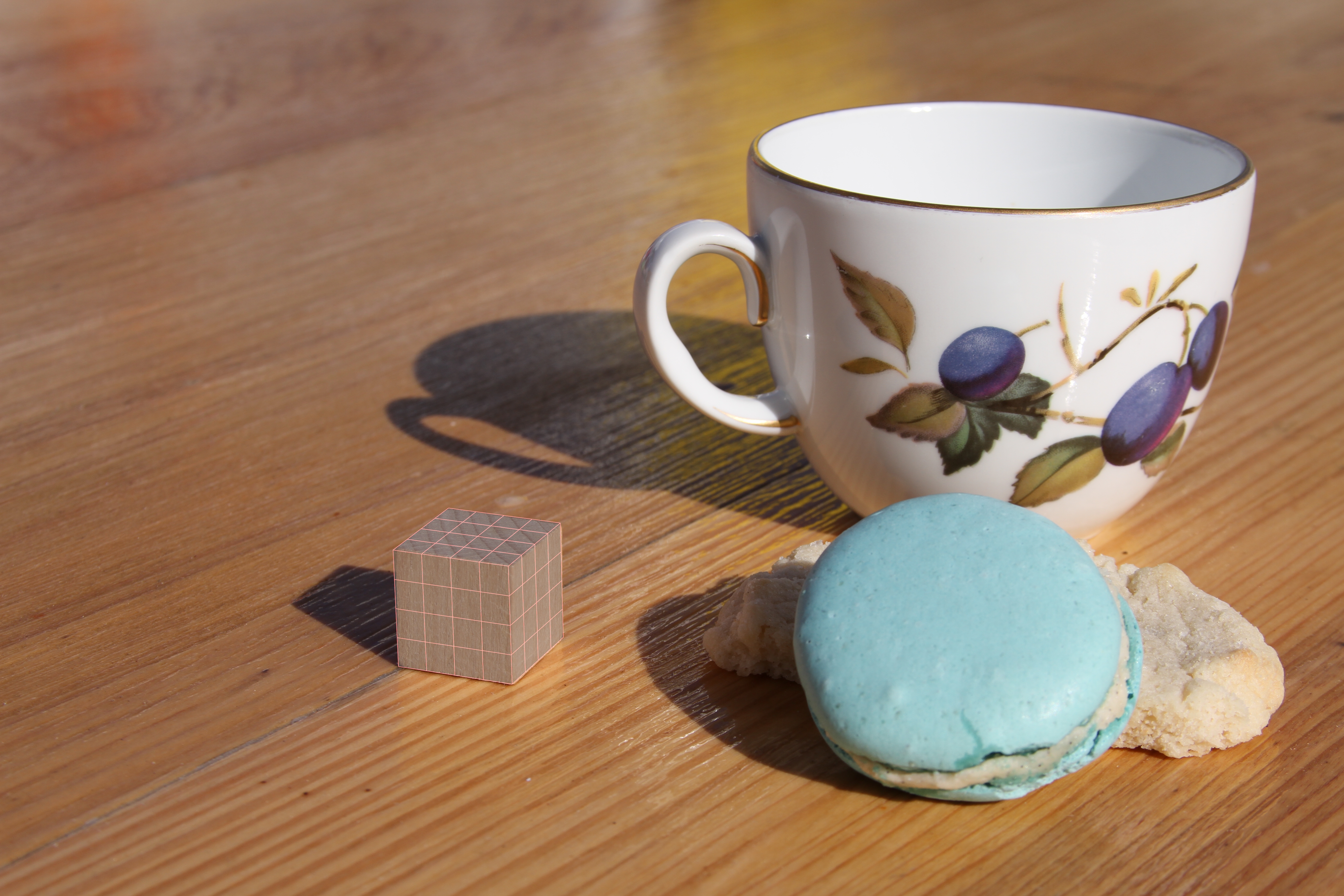
– cube photo: the original teacup in its position with a small cube in place of the twin
– chrome sphere: the original teacup with a chrome sphere in place of the twin
Here are examples of the photographs I took:

Step 2 – Teacup Model

Step 3 – Camera Setup in Maya and Cube Match
Once the basic teacup model had been completed and the proper photographs have been taken, it was time to set up the scene in Maya. In order to do this, a render camera needs to be created with an image plane attached to it. The image plane connects an image to the camera so that it can be viewed through the camera at all times; in this case, the image chosen was the photograph with the cube. Three pieces of information was required to properly set up the camera in Maya to match the real-world conditions of my photography session:
1. the size of the final photos
2. the camera used to take the photo
3. the focal length
I then used a focal length converter (http://www.digified.net/focallength/) to calculate the appropriate focal length for my camera in Maya. That way I could be sure that each aspect of the project – camera information, image pixel size and aspect ratio, real-world measurement of the cube – was accurate so that I could better match the CG cup to the live plate. Finally, I set the size of my renderable camera to match the size of the photograph. Before working with the CG teacup model, its important to create a basic cube primitive and align it with the cube in the photograph. This is done by snapping the pivot point of the cube to one of the bottom corners and then snapping that point to the origin of the grid in Maya. From there, the cube itself is not actually being translated; I looked through the render camera and positioned it accordingly so that the two cubes matched as closely as possible.
Step 4 – Lighting and Shadow Match
Once the CG cube was lined up with the original cube I created a ground plane underneath the cube and placed the first spotlight in the scene, and matched the shadow of the cube in Maya to that of the cube in the photograph. Then I placed a sphere in the scene and enlarged it to encompass all of my objects – this will become the final gather dome that acts as a fill or bounce light. In order to activate the final gather lighting I applied a surface shader to the sphere and connected the photograph of the chrome sphere (cropped) to it. This inevitably created a seam in the sphere which was to be positioned in the center of the frame. Shown below is the cube-shadow match, the cropped image of the chrome sphere, a render of the surface shader on the dome, and the the centered seam from the point of view of the render camera.


Step 5 – Teacup
I replaced the cube with the CG model of the teacup and created a shader for the cup with a texture map of the pattern from the original. In order to do this, I photographed the cup’s pattern from 3-4 angles and stitched them together in Photoshop. Then I worked between Maya and Photoshop to scale, position and color correct the pattern according to the original in the photo. Once all of this was in place and the basic attributes for the shader were established (to resemble porcelain), I focused on matching the specular highlights from my shader to the original.

Step 6 – Render Layer Creation
Once the shadows and specular highlights have been matched, I went on to create layers in Maya. The layers are created specifically for individual components of the scene, such as the teacup with the diffuse map, the teacup with specularity, the shadow of the cup or even individual lights. The breakdown of these characteristics into layers allows for more control and precision in compositing. When the original Maya scene file has been broken down into layers, the layers are then batch rendered and composited in Nuke for the final ‘Match to Live’ piece.
I have 5 layers in my scene:
1. DiffuseLight – ground plane, teacup, and spotlight; no specularity or reflectivity in shader
2. DiffuseFill – ground plane, teacup and final gather dome
3. Specularity – teacup and final gather dome; no diffuse color (only specularity and reflectivity remain on shader)
4. Shadow – ground plane, teacup and spotlight; primary visibility of teacup turned off
5. EnvironmentReflectivity – teacup and final gather dome; special reflective material created and applied to teacup
The following breakdown video shows how each render layer contributed to the final look of the ‘Match to Live’ project:
